本帖最后由 bubblegum 于 2015-11-29 20:18 编辑
Verilog is a type of Hardware Description Language (HDL). Verilog is one of the two languages used by education and business to design FPGAs and ASICs. If you are unfamilliar with how FPGAs and ASICs work you should read this page for an introduction to FPGAs and ASICs. Verilog and VHDL are the two most popular HDLs used. Compared to traditional software languages such as Java or C, Verilog works very differently. Let's get started by looking at a simple example. First we will create a Verilog file that describes an And Gate. As a refresher, a simple And Gate has two inputs and one output. The output is equal to 1 only when both of the inputs are equal to 1. Below is a picture of the And Gate that we will be describing with Verilog. 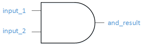 An And Gate
Let's get to it! One fundamental unit of Verilog is called a wire. For now let’s assume that a wire can only be a 0 or a 1. Here is some basic wire logic: wire and_temp;
assign and_temp = input_1 & input_2;
We are creating a wire called and_temp on the first line of code. On the second line of the code, we are taking the wire that we created and we are assigning the wire. To assign it, we are using the Boolean AND function which in Verilog is the Ampersand (&). If you were to describe the code shown above, you might say, "The signal and_temp gets input_1 AND-ed with input_2." Input_1 and Input_2 are inputs to this piece of Verilog Code. Let's show the complete list of inputs and outputs. This is done in themodule definition. Module is a reserved keyword in Verilog which shows the creation of a block of code with defined inputs and outputs. module example_and_gate
(
input_1,
input_2,
and_result);
input input_1;
input input_2;
output and_result;
This is your basic module. It defines our module called example_and_gate and 3 signals, 2 inputs and 1 output. Let's put everything together to finish the file. The only thing we are missing is the assignment of the output and_result. One other note, // in Verilog is used for a comment. module example_and_gate
(
input_1,
input_2,
and_result);
input input_1;
input input_2;
output and_result;
wire and_temp;
assign and_temp = input_1 & input_2;
assign and_result = and_temp;
endmodule // example_and_gate
Congratulations! You have created your first Verilog file. Here's the full code: example_and_gate.v Does it seem like you had to write a lot of code just to create a stupid and gate? First of all, and gates aren’t stupid. Secondly, you are correct, HDLs take a lot of code to do relatively simple tasks. You can take some comfort in the fact that Verilog is at least less verbose than VHDL. Get used to the fact that doing something that was very easy in software will take you significantly longer in an HDL such as Verilog or VHDL. But just ask some software guy to try to generate an image to a VGA monitor that displays Conway’s Game of Life and watch their head spin in amazement! By the way, that video is created with an FPGA. You will be able to do that soon enough! http://www.nandland.com/verilog/tutorials/tutorial-introduction-to-verilog-for-beginners.html
| 


 提升卡
提升卡 置顶卡
置顶卡 沉默卡
沉默卡 喧嚣卡
喧嚣卡 变色卡
变色卡 千斤顶
千斤顶 照妖镜
照妖镜


 苏公网安备 32040002010688号